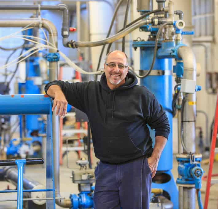
Optimizing Pump System Efficiency With PIPE-FLO
Case Study: Optimizing Pump System Efficiency With PIPE-FLO As part of the 12th International Conference on Energy Efficiency in Motor Driven Systems, our team set

Case Study: Optimizing Pump System Efficiency With PIPE-FLO As part of the 12th International Conference on Energy Efficiency in Motor Driven Systems, our team set

Give your operations and IT teams the tool they deserve. Discover the CPQ benefits for operations and IT here.

Give your operations and IT teams the tool they deserve. Discover the CPQ benefits for operations and IT here.

Give your operations and IT teams the tool they deserve. Discover the CPQ benefits for operations and IT here.

In the previous chapter of this series, we talked about the benefits of fluid flow software for visualizations and calculations and how integrating calculations and

Computer-aided design (CAD) and spreadsheet programs like Microsoft Excel enabled a major leap forward in fluid flow calculation, but even with these advancements, it’s still

While Excel is a staple in the engineering community, it has slowly become outdated and costly compared to modern solutions. By looking at the real-life

If your business uses fluid for any process or service, you likely have a fluid processing system in your facility. But you might be wondering:

From start to finish, projects encounter roadblocks. These challenges require analysis, planning, and management to stay on track. By using proper project lifecycle management (PLM),
| Cookie | Duration | Description |
|---|---|---|
| __hssc | 30 minutes | HubSpot sets this cookie to keep track of sessions and to determine if HubSpot should increment the session number and timestamps in the __hstc cookie. |
| __hssrc | session | This cookie is set by Hubspot whenever it changes the session cookie. The __hssrc cookie set to 1 indicates that the user has restarted the browser, and if the cookie does not exist, it is assumed to be a new session. |
| _GRECAPTCHA | 5 months 27 days | Google Recaptcha service sets this cookie to identify bots to protect the website against malicious spam attacks. |
| cookielawinfo-checkbox-advertisement | 1 year | Set by the GDPR Cookie Consent plugin, this cookie records the user consent for the cookies in the "Advertisement" category. |
| cookielawinfo-checkbox-analytics | 11 months | This cookie is set by GDPR Cookie Consent plugin. The cookie is used to store the user consent for the cookies in the category "Analytics". |
| cookielawinfo-checkbox-functional | 11 months | The cookie is set by GDPR cookie consent to record the user consent for the cookies in the category "Functional". |
| cookielawinfo-checkbox-necessary | 11 months | This cookie is set by GDPR Cookie Consent plugin. The cookies is used to store the user consent for the cookies in the category "Necessary". |
| cookielawinfo-checkbox-others | 11 months | This cookie is set by GDPR Cookie Consent plugin. The cookie is used to store the user consent for the cookies in the category "Other. |
| cookielawinfo-checkbox-performance | 11 months | This cookie is set by GDPR Cookie Consent plugin. The cookie is used to store the user consent for the cookies in the category "Performance". |
| CookieLawInfoConsent | 1 year | CookieYes sets this cookie to record the default button state of the corresponding category and the status of CCPA. It works only in coordination with the primary cookie. |
| elementor | never | The website's WordPress theme uses this cookie. It allows the website owner to implement or change the website's content in real-time. |
| JSESSIONID | session | New Relic uses this cookie to store a session identifier so that New Relic can monitor session counts for an application. |
| PHPSESSID | session | This cookie is native to PHP applications. The cookie stores and identifies a user's unique session ID to manage user sessions on the website. The cookie is a session cookie and will be deleted when all the browser windows are closed. |
| viewed_cookie_policy | 11 months | The cookie is set by the GDPR Cookie Consent plugin and is used to store whether or not user has consented to the use of cookies. It does not store any personal data. |
| Cookie | Duration | Description |
|---|---|---|
| __cf_bm | 30 minutes | Cloudflare set the cookie to support Cloudflare Bot Management. |
| _icl_visitor_lang_js | 1 day | WPML sets this cookie to store the redirected language. |
| drift_aid | 1 year 1 month 4 days | Drift sets this cookie as a session identifier token. It is used to tie the visitor on your website to a current website session within the Drift system. This enables session-specific features, such as popping up a message only once during a 30 minute session to prevent a disruptive experience. |
| drift_campaign_refresh | 30 minutes | Drift sets this cookie as a unique ID for the specific user. This allows the website to target the user with relevant offers through its chat functionality. |
| driftt_aid | 1 year 1 month 4 days | Drift sets this cookie as an anonymous identifier token. As people come onto the site, they will get this cookie. |
| li_gc | 5 months 27 days | Linkedin set this cookie for storing visitor's consent regarding using cookies for non-essential purposes. |
| lidc | 1 day | LinkedIn sets the lidc cookie to facilitate data center selection. |
| UserMatchHistory | 1 month | LinkedIn sets this cookie for LinkedIn Ads ID syncing. |
| wp-wpml_current_language | session | WordPress multilingual plugin sets this cookie to store the current language/language settings. |
| wpml_browser_redirect_test | session | This cookie is set by WPML WordPress plugin and is used to test if cookies are enabled on the browser. |
| Cookie | Duration | Description |
|---|---|---|
| __lotl | 5 months 27 days | Lucky Orange sets this cookie to identify the traffic source URL of the visitor's original referrer, if any. |
| _lo_uid | 1 year 1 month 4 days | Lucky Orange sets this cookie as a unique identifier for the visitor. |
| _lo_v | 1 year | Lucky Orange sets this cookie to identify the total number of visitor's visits. |
| _lorid | 10 minutes | Lucky Orange sets this cookie to record the current ID of visitors. |
| Cookie | Duration | Description |
|---|---|---|
| __hstc | 5 months 27 days | Hubspot set this main cookie for tracking visitors. It contains the domain, initial timestamp (first visit), last timestamp (last visit), current timestamp (this visit), and session number (increments for each subsequent session). |
| _fbp | 3 months | Facebook sets this cookie to display advertisements when either on Facebook or on a digital platform powered by Facebook advertising after visiting the website. |
| _ga | 1 year 1 month 4 days | Google Analytics sets this cookie to calculate visitor, session and campaign data and track site usage for the site's analytics report. The cookie stores information anonymously and assigns a randomly generated number to recognise unique visitors. |
| _ga_* | 1 year 1 month 4 days | Google Analytics sets this cookie to store and count page views. |
| _gcl_au | 3 months | Google Tag Manager sets the cookie to experiment advertisement efficiency of websites using their services. |
| _gd_session | 4 hours | This cookie is used for collecting information on users visit to the website. It collects data such as total number of visits, average time spent on the website and the pages loaded. |
| _gd_svisitor | 1 year 1 month 4 days | This cookie is set by the Google Analytics. This cookie is used for tracking the signup commissions via affiliate program. |
| _gd_visitor | 1 year 1 month 4 days | This cookie is used for collecting information on the users visit such as number of visits, average time spent on the website and the pages loaded for displaying targeted ads. |
| AnalyticsSyncHistory | 1 month | Linkedin set this cookie to store information about the time a sync took place with the lms_analytics cookie. |
| CONSENT | 2 years | YouTube sets this cookie via embedded YouTube videos and registers anonymous statistical data. |
| hubspotutk | 5 months 27 days | HubSpot sets this cookie to keep track of the visitors to the website. This cookie is passed to HubSpot on form submission and used when deduplicating contacts. |
| ifso_visit_counts | 1 year | If So sets this cookie to store number of visits. |
| ln_or | 1 day | Linkedin sets this cookie to registers statistical data on users' behaviour on the website for internal analytics. |
| vuid | 1 year 1 month 4 days | Vimeo installs this cookie to collect tracking information by setting a unique ID to embed videos on the website. |
| Cookie | Duration | Description |
|---|---|---|
| bcookie | 1 year | LinkedIn sets this cookie from LinkedIn share buttons and ad tags to recognize browser IDs. |
| bscookie | 1 year | LinkedIn sets this cookie to store performed actions on the website. |
| li_sugr | 3 months | LinkedIn sets this cookie to collect user behaviour data to optimise the website and make advertisements on the website more relevant. |
| VISITOR_INFO1_LIVE | 5 months 27 days | YouTube sets this cookie to measure bandwidth, determining whether the user gets the new or old player interface. |
| YSC | session | Youtube sets this cookie to track the views of embedded videos on Youtube pages. |
| yt-remote-connected-devices | never | YouTube sets this cookie to store the user's video preferences using embedded YouTube videos. |
| yt-remote-device-id | never | YouTube sets this cookie to store the user's video preferences using embedded YouTube videos. |
| yt.innertube::nextId | never | YouTube sets this cookie to register a unique ID to store data on what videos from YouTube the user has seen. |
| yt.innertube::requests | never | YouTube sets this cookie to register a unique ID to store data on what videos from YouTube the user has seen. |
| Cookie | Duration | Description |
|---|---|---|
| _an_uid | 7 days | No description available. |
| _gd1687981540406 | session | Description is currently not available. |
| 6suuid | 1 year 1 month 4 days | No description available. |
| ifso_page_visits | 1 year 1 month 4 days | No description available. |
| oribi_cookie_test | session | Description is currently not available. |
| oribili_user_guid | 1 year | Description is currently not available. |